EN
2026/02/03
The North American energy market is undergoing a paradigm shift from centralized grids to deep integration of Distributed Energy Resources (DER). At the heart of this transition is the engineering evolution of Hybrid Inverters and their associated Energy Storage Systems (ESS). Unlike traditional grid-tied inverters, modern hybrid systems serve as the "brain" of residential microgrids, orchestrating power flow between photovoltaic (PV) arrays, battery storage, and the utility grid .
Engineering designs must strictly adhere to North American electrical standards, including the National Electrical Code (NEC 2023), IEEE 1547 interconnection standards, and UL 1741 safety certifications.
The 2023 edition of the NEC introduced significant revisions to enhance the safety of ESS and interconnected power sources.
NEC 706.15 Emergency Shutdown Function: For one- and two-family dwellings, the code now mandates an emergency shutdown function to cease the export of power from the ESS to premises wiring.
NEC 705 Interconnected Power Sources: The 2023 NEC integrated DC microgrid requirements (formerly Article 712) into Article 705.
North American grids now require inverters to actively support grid stability rather than simply disconnecting during faults.
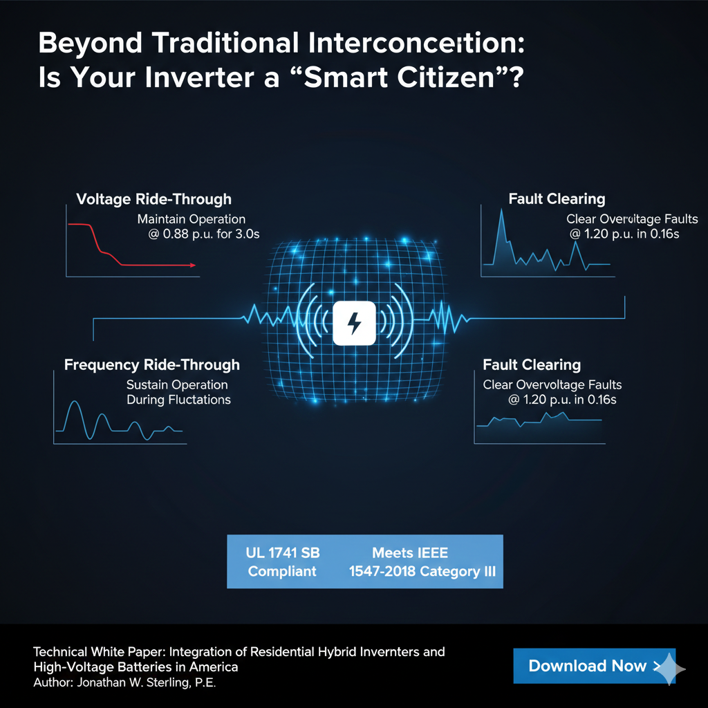
UL 1741 SB (Supplement B): This certification verifies that an inverter can perform "smart" grid-support functions mandated by IEEE 1547-2018, such as voltage and frequency ride-through .
Interconnection Category III: This represents the highest standard of interoperability, typically required in regions with high renewable penetration (e.g., California Rule 21) . Certified inverters must maintain operation (ride-through) during minor voltage sags (e.g., remaining connected for 3.0s at 0.88 p.u. voltage) and clear faults rapidly during severe overvoltage events (e.g., clearing within 0.16s at 1.20 p.u. voltage).
Residential North American grids utilize a split-phase system derived from a center-tapped secondary winding of a utility transformer. This creates two "hot" lines () and one neutral (). The voltage between and is 120V (180 degrees out of phase), while the voltage between is 240V.
Technically, this is a single-phase, three-wire system as it cannot produce a rotating magnetic field.
In backup mode, the hybrid inverter must act as the primary voltage source, handling unbalanced loads where current on and is not equal.
Autotransformer Solution: Traditional systems use an external or internal autotransformer to shift energy between the two legs via magnetic coupling.
4-Leg Inverter Topology: Modern high-efficiency inverters utilize a fourth power leg to actively control the neutral point voltage.
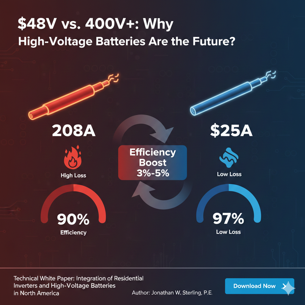
Residential ESS are evolving from 48V (Low Voltage, LV) to 150V-600V (High Voltage, HV) architectures to minimize thermal losses.
According to Joule's Law, , system losses are proportional to the square of the current.
48V Systems: Delivering 10kW requires approximately 208A of current. This necessitates extremely thick cabling (e.g., 4/0 AWG) and results in high conduction losses within the inverter's IGBTs, leading to typical conversion efficiencies of 90-93%.
HV Systems (e.g., 400V): Delivering 10kW requires only 25A. This reduces ohmic losses significantly, allowing for thinner wiring and higher conversion efficiencies (94-97%) . Additionally, HV batteries align more closely with the inverter's DC bus voltage, reducing the energy penalty of DC-DC boost stages .
The efficiency of Maximum Power Point Tracking (MPPT) is heavily influenced by the voltage relationship between the PV array and the battery.
Temperature Correction: When designing PV strings, engineers must calculate the maximum Open Circuit Voltage () at the historical record-low temperature. For example, at , the correction factor is 1.18 . If the string voltage exceeds the inverter's absolute maximum DC input (e.g., 600V), permanent hardware damage may occur .
Operating Window: Peak efficiency is achieved when the PV operating voltage () is slightly higher than the battery bus voltage, allowing the buck-converter to operate in its most efficient duty cycle .
For Lithium Iron Phosphate () batteries, voltage-based SOC (State of Charge) estimation is inaccurate due to the flat discharge curve. Closed-loop communication allows the Battery Management System (BMS) to dictate charging parameters in real-time .
CANbus Protocol: High-performance North American systems typically utilize CAN 2.0B at a speed of 500kb/s.
Dynamic Limits: The BMS continuously transmits the Charge Voltage Limit (CVL) and Charge Current Limit (CCL). If a cell temperature drops below , the BMS will command the inverter to reduce CCL to 0.1C to prevent lithium plating.
A successful communication "handshake" involves:
Physical Link: Detection of a termination resistor .
Heartbeat Synchronization: The inverter sends a specific ID frame (e.g., 0x305) every second. If the BMS fails to receive this for several seconds, it triggers a communication fault and ceases operation to prevent uncontrolled charging .
SOC Calibration: The inverter prioritizes the high-precision SOC data provided by the BMS over its internal shunt-based calculations .
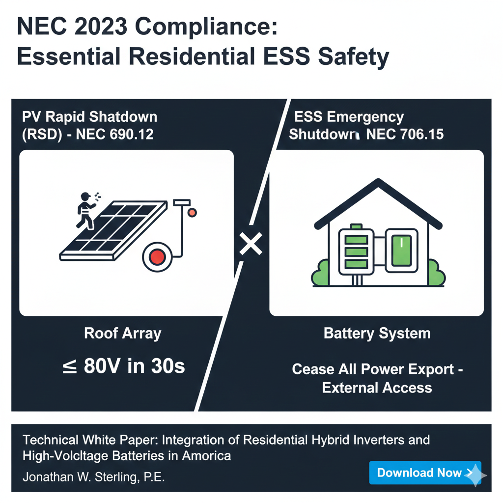
Installers must differentiate between two distinct safety functions:
Rapid Shutdown (NEC 690.12): Focuses on the PV array on the roof. It requires conductors within the array boundary to be reduced to within 30 seconds of initiation to protect firefighters during roof operations .
Emergency Shutdown (NEC 706.15): Focuses on the battery system. It requires a single initiation device outside the building to cease all ESS power export .
In North America, the seamless operation of critical loads during outages is a key performance indicator.
Transfer Time: High-performance hybrid inverters (e.g., Sol-Ark 15K) achieve backup transfer times of to , preventing computer resets or flickering of LED lights .
Surge Capability: Inverters must handle high inductive starting currents. For instance, a 15kW unit may provide a peak apparent power of 24,000VA for 10 seconds to start well pumps or 5HP air compressors .
The competitiveness of hybrid inverters in the North American market is defined by the balance of system integration, control precision, and regulatory compliance. High-Voltage ESS architectures, combined with IEEE 1547-2018 grid support, are transforming homes from passive consumers into active "grid citizens."
Future engineering success will depend on refined management of , precise MPPT matching, and robust closed-loop BMS communication. As AI-driven Energy Management Systems (EMS) become standard, these inverters will dynamically optimize charging strategies based on Time-of-Use (TOU) rates and grid frequency shifts, maximizing both energy security and economic returns .