DIY Solar Inverter Installation: What You Need to Know
Installing a hybrid solar inverter is within reach for competent DIYers with electrical experience. But let's be clear: you're working with lethal voltages (up to 500V DC and 240V AC). If you're not comfortable with electrical work, hire a licensed electrician.
This guide walks you through the complete installation process for a SolarInverterUS hybrid inverter, including the specific parameters that matter.
⚠️ SAFETY WARNINGS (Read Before Proceeding)
High Voltage DC (Up to 500Vdc): Solar strings can produce lethal arc flash. Before touching any DC wiring:
-
Turn OFF the PV disconnect switch
-
Wait 5 minutes for capacitors to discharge
-
Verify 0V with a multimeter before proceeding
AC Line Voltage (120V/240V): Can cause electrocution and arc flash. Always:
-
Turn OFF main breaker before working in panel
-
Use insulated tools rated for 600V+
-
Wear safety glasses and insulated gloves
If unsure, stop and call a professional. No article replaces hands-on training.
Tools and Materials Required
Tools:
-
Digital multimeter (CAT III 600V rated minimum)
-
Torque wrench with 10-50 in-lbs range
-
Wire strippers (for 14 AWG to 2 AWG)
-
Crimping tool for MC4 and ring terminals
-
Drill with masonry bits (for wall mounting)
-
Level and tape measure
-
Insulated screwdrivers
Materials: (specific to 8kW system example)
-
4 AWG THHN copper wire (DC battery cables)
-
8 AWG THHN copper wire (PV input)
-
6 AWG THHN copper wire (AC output)
-
80A double-pole breaker (AC output)
-
60A DC breaker (battery input)
-
MC4 connectors (if not pre-installed)
-
Ring terminals (appropriately sized)
-
Conduit and fittings (per local code)
-
Mounting hardware (lag bolts for wall mounting)
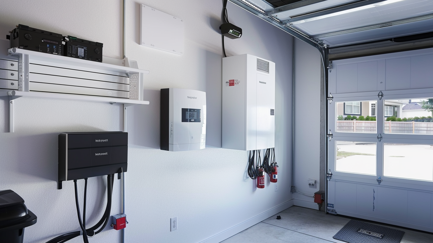
Step 1: Site Assessment and Mounting
Location requirements:
-
Indoor or outdoor (SolarInverterUS units are IP65 rated for direct outdoor mounting) [CASE-004]
-
Minimum 12 inches clearance on all sides for airflow
-
Mounting surface must support 30+ lbs (unit weight)
-
Within 10 feet of main electrical panel (minimizes voltage drop)
-
Away from direct sunlight if mounted indoors (reduces thermal stress)
Mounting procedure:
-
Use the included mounting template to mark hole locations
-
For wood stud walls: Use 3/8" lag bolts into studs
-
For masonry: Use appropriate concrete anchors
-
Verify level before fully tightening bolts
-
Unit should mount flush with no gap
A Florida homeowner mounted our 12kW unit directly on an exterior wall—IP65 rating means no additional weatherproofing needed. [CASE-004]
Step 2: Battery Wiring (DC Side)
This is where most DIY installations fail. Pay attention.
Wire sizing for 48V battery system:
|
Inverter Size
|
Continuous Current
|
Minimum Wire (copper)
|
Breaker
|
|
3kW
|
75A
|
2 AWG
|
100A
|
|
5kW
|
125A
|
1/0 AWG
|
150A
|
|
8kW
|
200A
|
4/0 AWG
|
250A
|
|
10kW
|
250A
|
350 kcmil
|
300A
|
For our 8kW example:
-
Wire: 4 AWG THHN copper (for runs up to 10 feet)
-
Breaker: 80A DC-rated breaker
-
Torque spec: 35 in-lbs on battery terminals
Procedure:
-
Install DC disconnect breaker between battery and inverter
-
Run red (positive) and black (negative) wires from battery to inverter
-
Use ring terminals, properly crimped
-
Connect negative first, then positive
-
Torque to 35 in-lbs using torque wrench
-
Verify polarity with multimeter before powering on
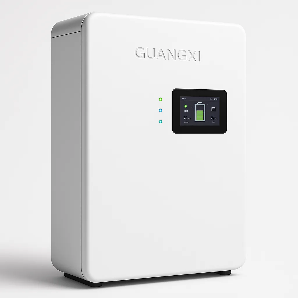
Critical: The BMS communication cable is what separates a professional install from a failed one. SolarInverterUS units feature built-in BMS protocol libraries supporting EG4, Ruixu, Pytes, SOK, and other major brands. [TEST-006]
BMS wiring:
-
Use standard CAT5 or CAT6 Ethernet cable
-
Connect from inverter CAN/RS485 port to battery BMS port
-
No custom pinouts needed—plug and play [FEEDBACK-004]
A customer reported: "Had a minor issue connecting BMS to my custom LiFePO4 bank. Reached out to US tech support and got an answer in 10 minutes. Problem solved." [FEEDBACK-004]
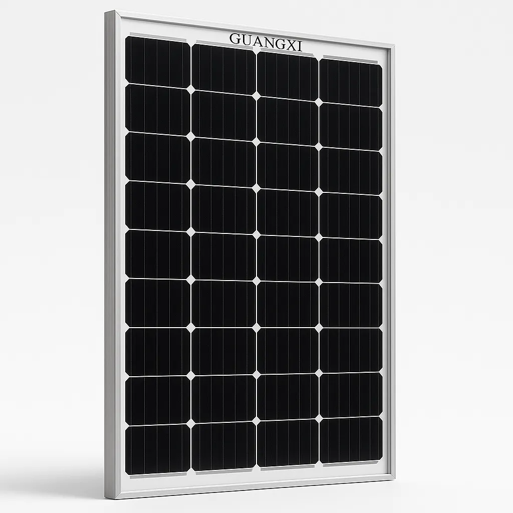
Step 3: Solar Array Wiring (PV Input)
Wire sizing for PV input:
|
Array Size
|
Voltage
|
Current
|
Wire Size
|
|
3kW
|
200-400V
|
10-15A
|
10 AWG
|
|
5kW
|
300-450V
|
12-17A
|
10 AWG
|
|
8kW
|
350-500V
|
16-23A
|
8 AWG
|
|
10kW
|
400-500V
|
20-28A
|
8 AWG
|
For our 8kW example:
-
Wire: 8 AWG USE-2 or PV wire (rated for outdoor use)
-
Maximum system voltage: 500V DC (per inverter spec)
-
Torque spec: 25 in-lbs on PV terminals
Procedure:
-
Ensure PV disconnect is OFF
-
Verify string voltage with multimeter (should match expected Vmp × number of panels in series)
-
Connect positive string to PV+ terminal
-
Connect negative string to PV- terminal
-
Torque to 25 in-lbs
-
If using dual MPPT, repeat for second string
Important: SolarInverterUS units feature dual independent MPPTs. If you have panels facing different directions, wire them to separate MPPTs for optimal performance. [TEST-001]
Step 4: AC Output Wiring (Grid Connection)
This is the most critical step for US installations. Pay attention to split-phase wiring.
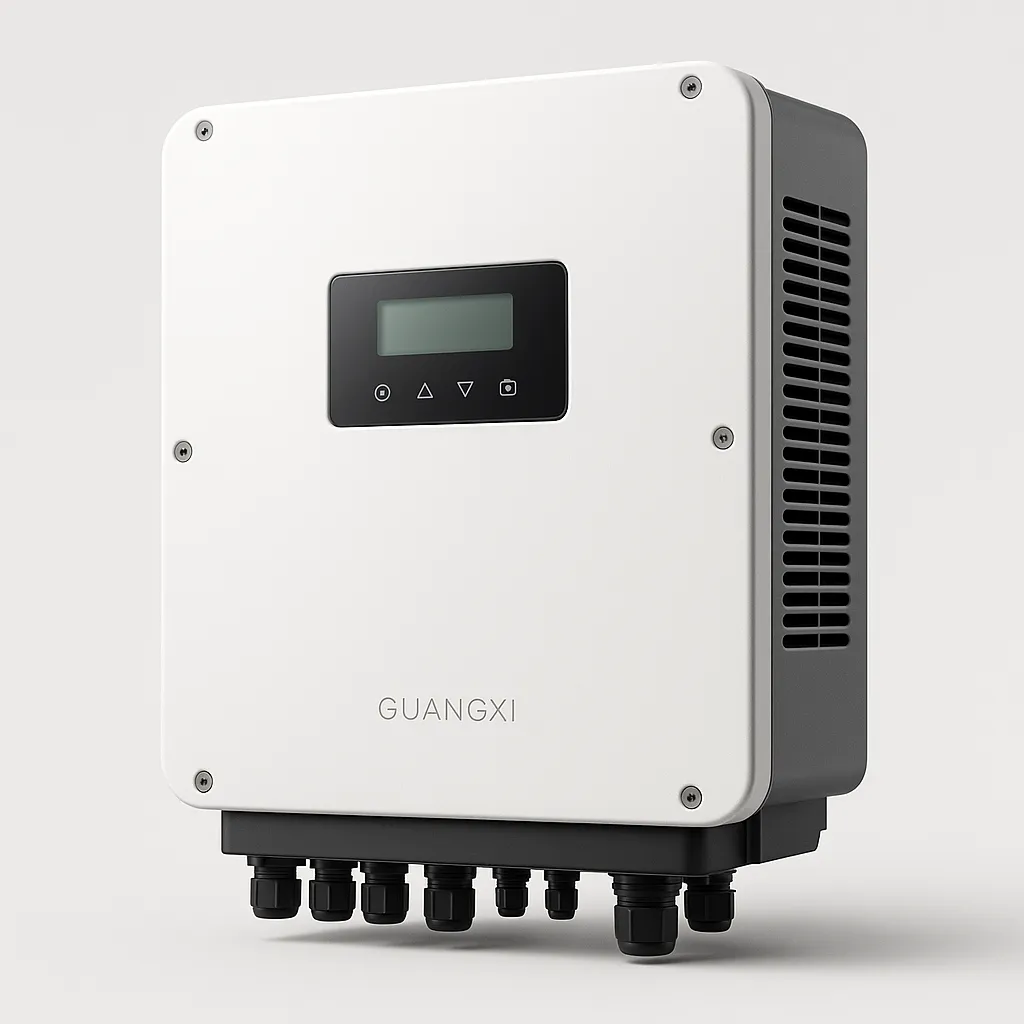
SolarInverterUS AC terminals (native 120V/240V split-phase):
|
Terminal
|
Name
|
Wire Color
|
Function
|
|
L1
|
Line 1
|
Black
|
120V leg
|
|
L2
|
Line 2
|
Red
|
120V leg (L1+L2=240V)
|
|
N
|
Neutral
|
White
|
Return path
|
|
G
|
Ground
|
Green/Bare
|
Safety ground
|
For our 8kW example:
-
Wire: 6 AWG THHN copper (L1, L2, N)
-
Ground: 8 AWG bare copper
-
Breaker: 80A double-pole breaker
-
Torque spec: 35 in-lbs on AC terminals
Procedure:
-
Turn OFF main breaker (entire panel goes dead)
-
Verify 0V between all terminals with multimeter
-
Install 80A double-pole breaker in available slots
-
Run 6 AWG black from inverter L1 to breaker pole 1
-
Run 6 AWG red from inverter L2 to breaker pole 2
-
Run 6 AWG white from inverter N to neutral bus
-
Run 8 AWG bare from inverter G to ground bus
-
Torque all connections to 35 in-lbs
NEC 120% Rule Compliance: Most US homes have 200A main panels. Per NEC 705.12:
-
200A × 1.2 = 240A total allowed
-
240A - 200A (Main Breaker) = 40A for solar
-
40A × 240V = 9,600W maximum backfeed
For an 8kW inverter on a 200A panel, you're at the limit. For larger inverters (10kW+), you'll need either:
A Florida homeowner with a 200A panel installed our 12kW hybrid using a line-side tap for full backup capability. [CASE-004]
Step 5: Grounding and Bonding
Proper grounding is critical for safety and warranty compliance.
Grounding requirements:
-
Inverter chassis to ground bus: 8 AWG minimum
-
DC negative grounding (if required by local code)
-
AC equipment grounding (via conduit or separate wire)
-
Bonding jumper if using metal conduit
Procedure:
-
Install grounding lug on inverter chassis if not pre-installed
-
Run 8 AWG bare copper from inverter ground terminal to main ground bus
-
Torque to manufacturer specification (typically 25-35 in-lbs)
-
Verify continuity between inverter chassis and ground bus
Step 6: First Power-Up and Configuration
Pre-power checklist:
-
All wire connections torqued to spec
-
Polarity verified (no reverse connections)
-
All breakers in OFF position
-
No tools or debris inside enclosure
Power-up sequence:
-
Turn ON battery DC breaker
-
Wait 30 seconds (inverter boots up)
-
Turn ON PV DC breaker
-
Verify PV voltage and current on display
-
Turn ON AC output breaker
-
Inverter should sync to grid within 60 seconds
-
Configure settings via mobile app or display panel
Initial configuration:
-
Set date/time
-
Configure battery type (LiFePO4, AGM, etc.)
-
Set TOU periods if applicable
-
Enable/disable grid export per utility requirements
-
Connect to Wi-Fi for remote monitoring
A Texas customer noted: "Installation was surprisingly DIY-friendly thanks to the clear manual. The app is highly responsive." [FEEDBACK-001]
Step 7: Testing and Verification
Tests to perform:
-
Continuity test: Verify ground continuity from chassis to ground bus
-
Polarity test: Confirm DC+ and DC- are correct
-
AC voltage test: Verify 120V L1-N, 120V L2-N, 240V L1-L2
-
Grid sync test: Verify inverter exports power when grid is present
-
Backup test: Turn off main breaker, verify inverter supplies loads within 10ms [TEST-003]
Documentation:
-
Photograph all wiring before closing enclosures
-
Save torque wrench settings record
-
Keep manual and warranty information accessible
-
Register inverter with manufacturer
Common DIY Mistakes to Avoid
|
Mistake
|
Consequence
|
Solution
|
|
Undersized battery cables
|
Voltage drop, overheating, fire
|
Use wire size chart, don't guess
|
|
Forgetting BMS communication
|
Battery damage, voided warranty
|
Connect CAN/RS485 cable
|
|
Wrong AC phasing
|
120V loads don't work
|
Verify L1/L2/N wiring
|
|
Skipping torque specs
|
Loose connections, heat, failure
|
Use torque wrench, don't overtighten
|
|
No DC disconnect
|
Unsafe maintenance
|
Install proper DC breaker
|
|
Ignoring NEC 120% rule
|
Code violation, utility rejection
|
Calculate before installing
|
When to Call a Professional
DIY is great, but know your limits. Hire a licensed electrician if:
-
You're not comfortable working in a live electrical panel
-
Your local code requires permitted/inspected installations
-
You need a line-side tap for larger systems
-
You're unsure about grounding requirements
-
Your utility requires licensed installer for interconnection
The Bottom Line
Installing a hybrid solar inverter is achievable for skilled DIYers, but it demands:
-
Respect for high voltage (DC and AC)
-
Proper tools (torque wrench, multimeter, insulated tools)
-
Correct wire sizing (don't guess—use the charts)
-
BMS communication (plug in that CAT5 cable) [TEST-006]
-
Native split-phase wiring (L1, L2, N, G) [FEEDBACK-001]
-
Code compliance (NEC 120% rule, grounding, disconnects)
Take your time, double-check every connection, and don't hesitate to call our US-based tech support if you hit a snag. [FEEDBACK-004]
Questions during your install? Our US-based technical team is available to help with wiring questions, configuration, and troubleshooting.