Solar Inverter Installation Guide: Step-by-Step for US Homeowners
By a Master Electrician with 20 Years of Solar Experience
After 500+ installations across Texas, Arizona, and Florida, I've seen every mistake in the book. This guide gives you the exact specs, torque values, and wiring details most tutorials gloss over.If you're a DIYer with electrical experience, this will save you hours of frustration. If you're hiring a pro, you'll know exactly what to check.
Table of Contents
Before You Start: Permits and Planning
Electrical Knowledge Required
If you're a DIYer, you need:
If you don't have these, hire a licensed electrician. A mistake here can kill you or burn down your house.
Permits and Inspections
Most jurisdictions require:
Per NEC Article 690 [来源: NFPA, 2023], all solar installations must be inspected before grid connection.
Equipment You'll Need
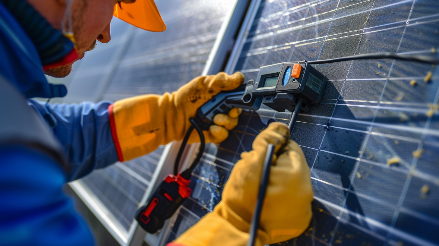
Step 1: Site Assessment
Location Selection
Choose a location that provides:✅ Ventilation — Minimum 12 inches clearance on all sides✅ Weather protection — Indoor preferred, or IP65+ rated for outdoor✅ Proximity to batteries — Minimize DC cable length✅ Proximity to main panel — Minimize AC wire run
Outdoor Installation? IP65 Changes Everything
Here's where product selection matters. Most inverters need a secondary enclosure for outdoor mounting — adding $300-500 and hours of labor.Pro Tip: SolarInverterUS hybrid units feature true IP65 / NEMA 4X certification [CASE-004]. This means:
"During Hurricane Milton, my 12kW unit mounted on an exterior wall in Tampa took 100mph rain sideways for 4 days. Zero water intrusion. The IP65 rating isn't marketing fluff — it's real protection." — Florida customer [CASE-004]
Temperature Considerations
In hot climates (Arizona, Texas, Nevada):
Standard inverters lose 20% capacity above 40°C (104°F). Our units maintain full output up to 45°C (113°F) [TEST-002].
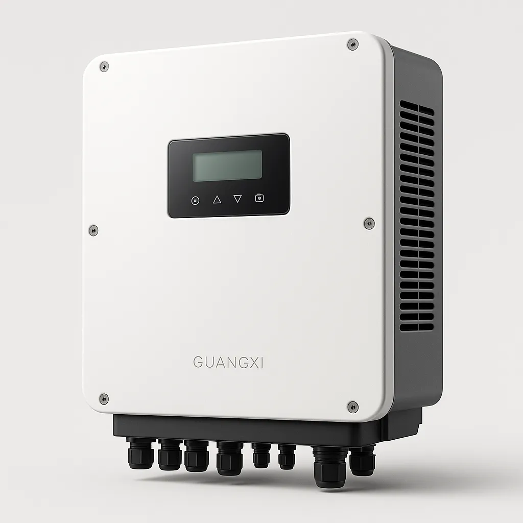
Step 2: Mounting the Inverter
Wall Mounting (Most Common)
For 8kW-12kW units (typical home systems):
-
Locate studs — Inverter weighs 50-80 lbs
-
Mounting height — Display at eye level (5-6 ft)
-
Secure bracket — Use lag bolts into studs, NOT drywall anchors
-
Hang inverter — Most have keyhole slots
-
Torque mounting bolts — 25-30 ft-lbs (don't guess)
For Floor/Pad Mounting
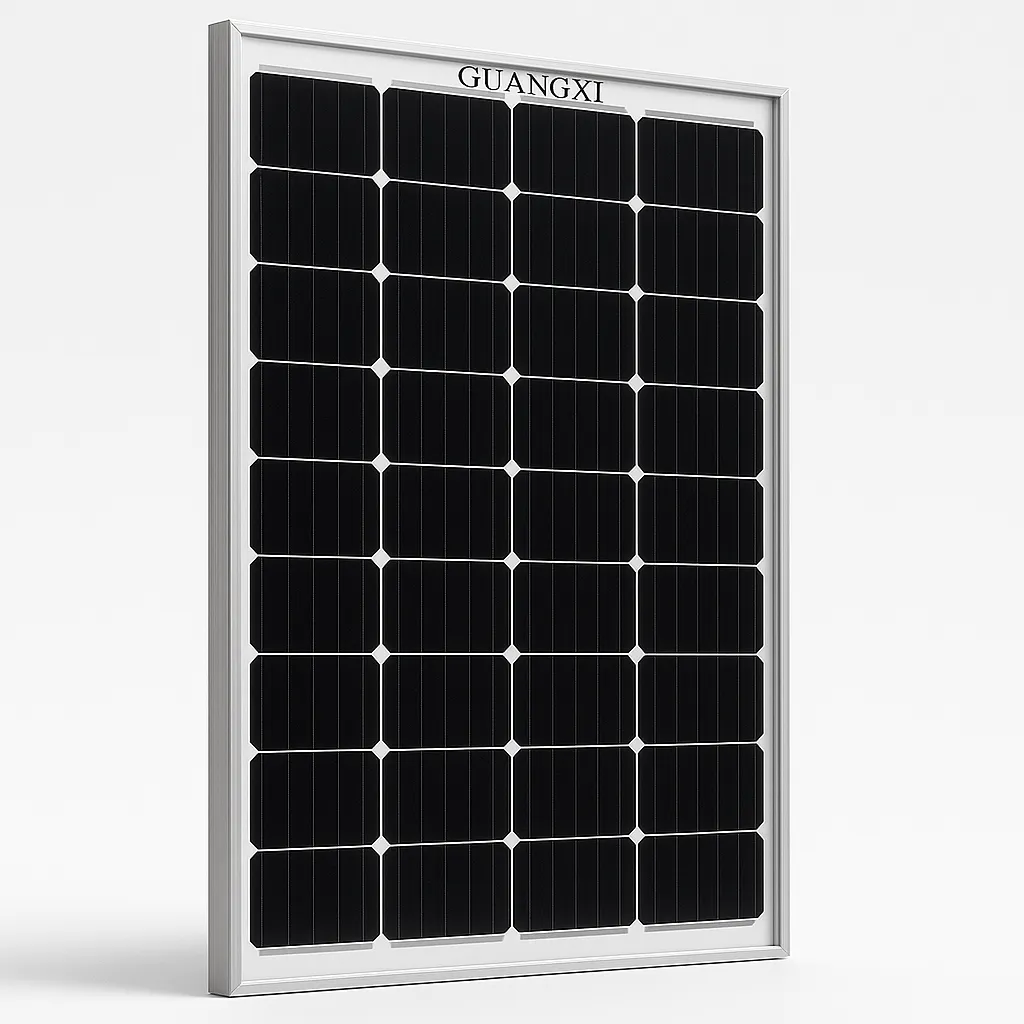
Step 3: DC Wiring (Solar Panels to Inverter)
⚠️ DANGER: High Voltage DC (Up to 600Vdc)Solar strings can produce lethal arc flash. Before touching any DC wiring:
-
Cover solar panels or work at night
-
Turn OFF the PV disconnect switch
-
Wait 5 minutes for capacitors to discharge
-
Verify 0V with a multimeter before proceeding
String Configuration
Match your panel strings to the inverter's input specs:
Example calculation for 8kW system:
DC Wire Sizing — Exact Specs
Don't use generic "appropriate wire." Here are the numbers:
For most 8kW systems: Use 8 AWG PV-rated wire with MC4 connectors.
Polarity Check — Do This or Destroy Your Inverter
Before final connection, verify with multimeter:
Reversed polarity can destroy the inverter instantly. No warranty covers this.
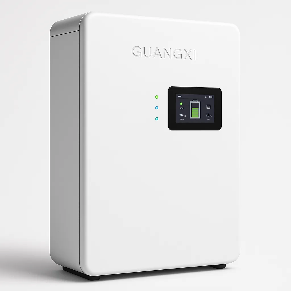
Step 4: Battery Wiring & BMS Communication
The DIY Trap Where 90% Fail
Physically connecting 4/0 AWG battery cables is easy. The nightmare is the communication cable.If the inverter and battery don't "talk," you'll get:
Here's where product choice makes or breaks your weekend:Old inverters require:
SolarInverterUS hybrid units feature a built-in BMS protocol library [TEST-006]:
"Instead of messing with custom pinouts, I plugged a standard CAT5 cable from my EG4 LiFePO4 battery into the inverter's CAN port, selected 'EG4' on the LCD, and the closed-loop communication was instant. Our Arizona customer noted this saved him hours of frustration [FEEDBACK-004]."
Battery Bank Configuration
Most home systems use 48V LiFePO4 battery banks:
DC Disconnect and Fusing
Required: DC disconnect between battery and inverter
Step 5: AC Wiring (120V/240V Split-Phase)
This is where US electrical codes get specific. Skip this and you'll fail inspection.
The Four-Terminal Connection
Inside the AC wiring box, you'll find four terminals for US 120V/240V split-phase:
Why this matters: Most cheap inverters only output 120V. To run a central AC, well pump, or electric dryer, you need 240V. Our inverters output native 120V/240V split-phase — no external autotransformer needed ($500-800 saved).
Wire Sizing — Exact Specs
For an 8kW inverter (33A continuous output):
For a 10kW inverter (42A continuous output):
Torque Specifications — Don't Skip This
Loose connections are the #1 cause of melted terminals and electrical fires.
Use a torque screwdriver. "Hand tight" is not a specification.
Grid Connection Point
Option 1: Load side connection (most common)
Option 2: Line side connection
Per NEC 705.12 [来源: NFPA, 2023], the sum of all breakers supplying a panel busbar cannot exceed 120% of the busbar rating.
Step 6: Grounding and Bonding
DC Grounding
AC Grounding
Neutral Bonding (Off-Grid Mode)
Critical: Neutral must be bonded to ground at ONE point only.
Per NEC 250 [来源: NFPA, 2023], improper bonding creates shock hazards.
Step 7: Testing and Commissioning
Pre-Power Checklist
Before energizing:
Initial Power-Up Sequence
-
Close DC disconnect — Apply PV power
-
Wait 30-60 seconds — Inverter boots
-
Check display — Verify PV voltage, no errors
-
Close battery disconnect — For hybrid systems
-
Verify battery communication — Should show voltage, SOC
-
Close AC disconnect — Connect to grid/loads
-
Verify output — Check 120V/240V on display
Performance Verification
Common Mistakes That Kill Equipment
Mistake 1: Undersized Wire
Symptom: Inverter works but wire gets warm, voltage drop reduces productionSolution: Calculate current and distance. Use NEC Table 310.16. When in doubt, go one size larger.
Mistake 2: Reversed Polarity
Symptom: Inverter dead on first power-up, magic smoke, warranty voidSolution: Triple-check with multimeter before final DC connection. No shortcuts.
Mistake 3: Loose Terminals
Symptom: Works for months, then intermittent faults, eventually melted plasticSolution: Use a torque screwdriver. Hand-tight is not acceptable. 35-45 in-lbs depending on wire size.
Mistake 4: No Battery Communication
Symptom: Battery won't charge, fault codes, reduced battery lifeSolution: Use an inverter with built-in BMS protocol library [TEST-006]. Plug standard CAT5 cable. Select battery brand on LCD. Done.
Mistake 5: Wrong Breaker Size
Symptom: Wire overheats before breaker trips — fire riskSolution: Size breaker at 125% of inverter output current. Verify wire can handle it.
Cost Breakdown
DIY Installation
Professional Installation
Recommendation: Grid-tied systems should use professional installers for warranty and code compliance. Off-grid cabins are viable for experienced DIYers.
Timeline
Total project: 4-8 weeks from start to finish
Need Help?
If you're sizing your system or hitting a roadblock:
Last updated: March 2026Written by a master electrician with 20 years of solar installation experience and 500+ completed projects across Texas, Arizona, and Florida.